Author: eido312
FINAL PROJECT – BLOG 3
The project has been successfully completed! The SpiceRight spice dispenser is now a real thing and it works quite well.
The 3d print went really well, the gear pieces came out looking like this:

The only issues here were that the holes on the small gears were too small (I sanded them out) and the snap fit pieces didn’t work at all. This was initially a huge problem I faced, but I found a solution pretty quickly with some tinkering. I put some tape on the joint of the snap fit pieces and this allowed the gears to snugly fit on and turn smoothly.

The gear lids were glued to the spice container lids with no issue.
The servo motors were glued to the back of the arduino, along with some cardboard supports – the idea being that the motors and these supports create a middle section of the device so the motors can be better tucked away.


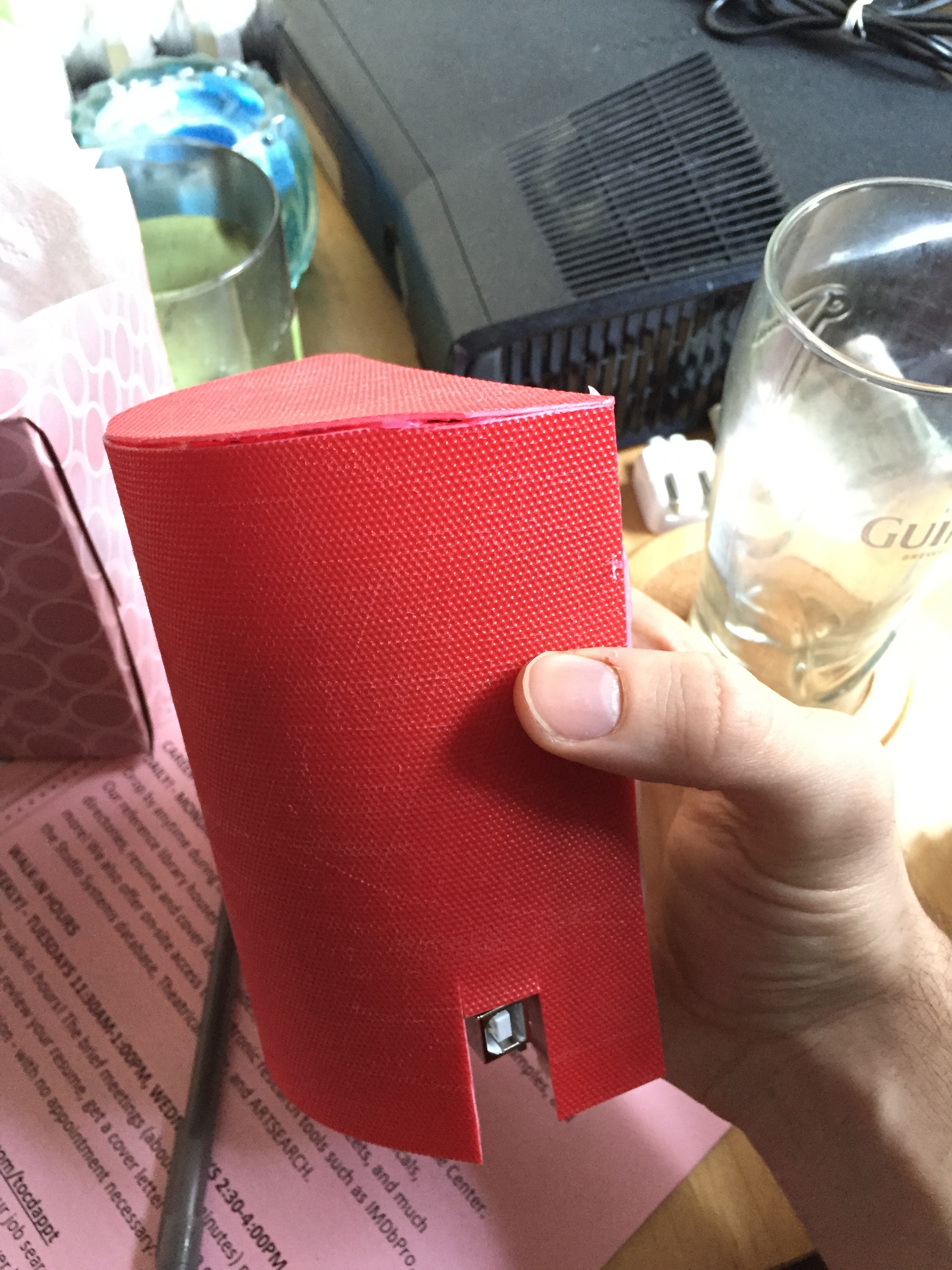
The housing went on nice and easy and looks great. It has a slight texture that makes it easy to grip.
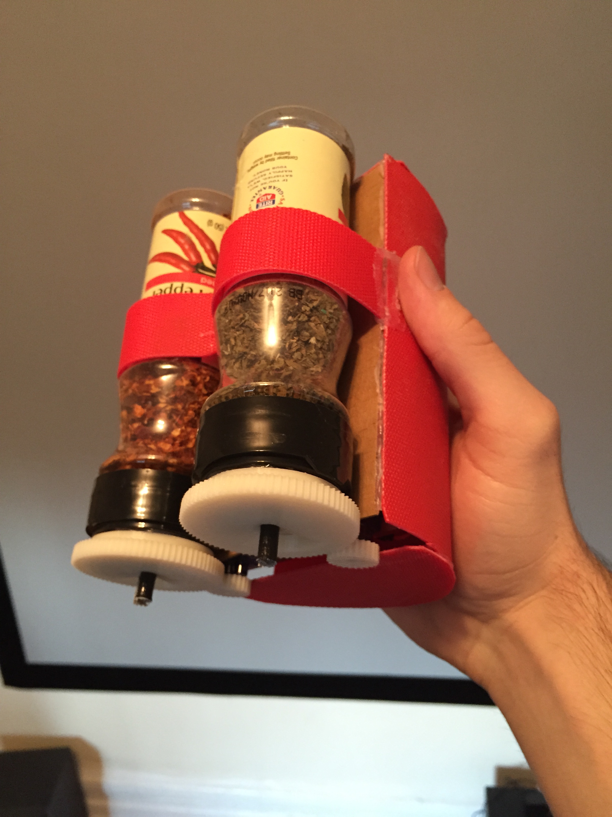
As I suspected, I had to calibrate the motor turns a bit in Arduino to get them opening just the right amount for each spice to dispense decently well. Actually the pepper flakes still didn’t dispense really well – it’d be better if the motor could turn a bit more or if the gear ratio was altered.
From the physical standpoint, the only thing the device is lacking that I had really hoped to implement was an easy switch system for different spices. Based on how carefully the gears have to align I couldn’t figure this out in time and opted to instead secure these two spices to the device.
Also the cord gets in the way a bit… bluetooth communication would be better for a future model, but I didn’t really expect to get that working for this.
From the software side, there’s 214 lines of code running in Processing that creates the user interface and records the dispensing times. The G4P library I downloaded and used was essential. I initially found it just to be able to more easily implement buttons and other GUI features, but it also had a timer function that made it really easy to time the opening of each spice container. Writing the code so that it would accurately record these times and recreate them was a big challenge for me, but through trial and error I got it working eventually. Discovering the timer function within the G4P library was also a big saving grace.
The Arduino code is pretty straightforward. Its 58 lines of code that really just receives serial messages from Processing and opens/closes the lids accordingly.

Processing and G4P made designing the GUI quite easy, and I am very pleased with the result.
I was able to complete this project successfully and make it fully functioning. Having said that, there are some areas left dive in to with a future version – bluetooth and removable containers.
I learned a lot about 3d printing from this project as it was my first (successful) 3d print. The level of detail the printer can manage is less than I expected, which is why my snap fit design failed.
Both this course and this project also taught me a lot about what goes in to physical design. Creating something that looks good, properly houses the machine components, and is easy to use is a very difficult task.
Finally, here’s the SpiceRight in action:
FINAL PROJECT – BLOG 2
There has been a solid amount of progress in the last week, with only a bumps along the way.
I first set out to plan exactly how the motors would power the doors/lids to the spice containers. I decided early on to create some kind of 3d printed part to handle this function, initially designing a sliding lid with a lever controlled by the servo motor. this design is picture below (the colors indicate separate physical parts).

Testing with a crude prototype made me quickly realize that this wouldn’t work too well. I then set about redesigning the lid and ended up going with a gear design. The servo motor controls a gear that turns another gear attached to a printed lid via a snap-fit piece. The three pieces are pictured here:
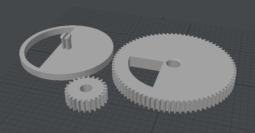
While there may be a small amount of trial and error with printing the pieces and getting them to fit right, I am very confident in this design. The snap-fit pieces and gears are designed based on designs I was able to find online, but I modeled them myself in Lightwave 3d.
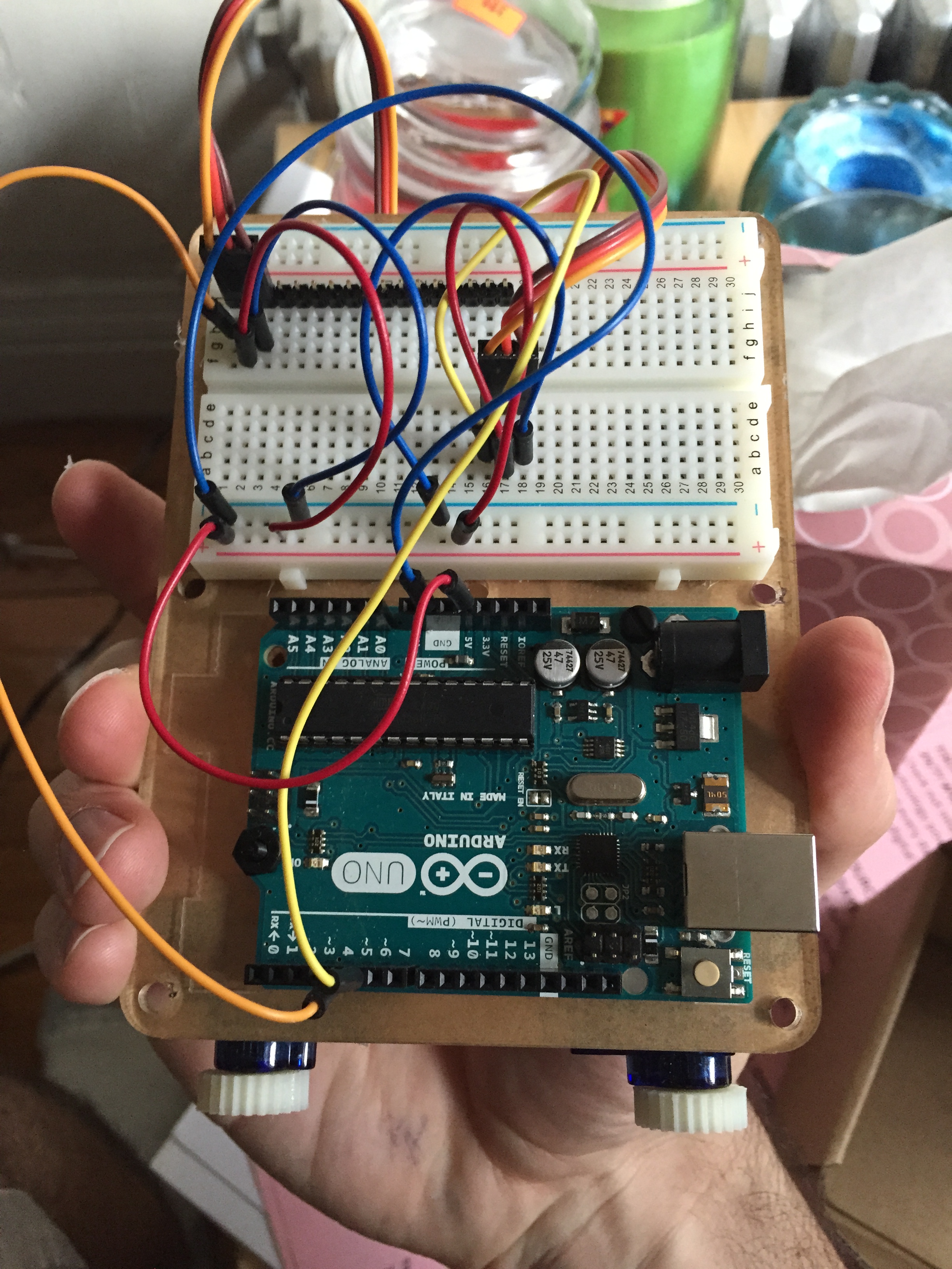
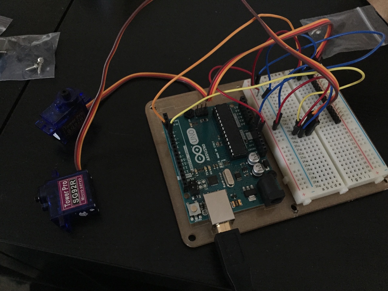
Beyond that, on the physical side I also received the additional servo motor I order and did the full Arduino assembly (nothing too fancy here) featuring two servo motors powered by the board and controlled separately by two digital pins.
I have a rough sketch here of how I think the final assembled device will look from the side and front:

For the housing I was looking for a material I could work with on my own without having to machine it and something that would look nice and create an attractive case. I found a thin, ply-able plastic cutting board that I think will work perfectly:

On the software side, I finished the Arduino programming pretty quickly – it simply controls the opening and closing of the two servo motor powered doors based on commands received by Processing. Once the device is assembled I anticipate having to tweak the degrees to which the motors turn, but that will be very simple.
Processing is handling the bulk of the software load, and I was very happy to discover a library (G4P) that adds simple GUI functionality without needed to manually code for buttons and such. I’m still exploring the possibilities within that library, but I have most of the code written. Initial functionality will include options to dispense spices for 2 preset recipes as well as to record your own and then re-dispense those – all of this will happen behind an intuitive GUI that the user interacts with while holding the device over their dish. If time permits I would add functions to dispense actual measurements as pre-calibrated by me (teaspoons/tablespoons), but I don’t see this as essential…
This week I will finish up the coding, do the 3d printing, and finish assembling the physical device. I am a little nervous about how well my 3d printed parts will work, but I have allowed some time for trial and error.
I’ve realized a bit late that bluetooth functionality (so you can hold the device away from the computer) would be a great addition, but I’m not sure I see myself getting to that by the deadline. I’m also a bit concerned that my physical assembly might not allow for the easy removal/switching of different spices, while this is an important part of the device’s use, I think it will still be very functional and useful if that capability doesn’t exist just yet…
FINAL PROJECT – BLOG 1
My idea for this project is to loosely build off of the concept of my Mechatronic Device project and create a dispenser of sorts for cooking spices. When I cook, I love to add different spices, but never bother to measure anything out – I simple judge it by eye. This creates great food, but makes it impossible to recreate the exact same thing twice. What I want to create is a software controlled dispenser that can record how long you choose to dispense a chosen spice and then can recall and execute the exact same dispensing later, or execute preloaded dispensing parameters based on a pre-existing recipes. This would eliminate the need for tediously measuring out many cooking ingredients.
The target audience of this project isn’t extremely specific – its anyone who likes to cook and likes to experiment with their cooking. The age range could be very broad, only really excluding young children. Therefore the device will have to be pretty appealing and intuitive, but doesn’t have to be childproof or attractive to a child.
My project streamlines an otherwise tedious process and solves a need for those who are more experimental in their cooking. It doesn’t solve a problem that can’t otherwise be worked out with careful measuring and note-taking, but it simplifies this process in a fun way.
My plan is to work mainly with the hardware I already have. For this first implementation of the device, I will create two dispenser motors, with removeable and replaceable spice containers so that a great number of spices could be controlled by the machine, 2 at a time. Because of the need for a back and forth movement I’m opting to work with servo motors. I have ordered a second servo motor so that each spice container has its own motor control.
As far as software goes, I plan on using Arduino with basic function only, and serial communication to Processing where I can run a basic GUI, control dispensing and do some text I/O to save and recall dispensing times for a given recipe. I may look in to finding a library for processing that might simplify some of that.
I will be working alone. I am a graduating film major with a minor in web design and applications.
MECHATRONIC DEVICE
The plan I set out with for this project was to create a mechanical movement that could control the dispensing of red pepper flakes, as one would put on a slice of pizza.
I chose to work with a servo motor so that I could easily create a back and forth motion. The rotation of the motor then had to be converted to the translation movement of the sliding door I created for the lid of the pepper flakes container. Essentially when a switch is triggered, the motor turns, pauses, and then turns back, causing the door to the spice container to slide open, let some flakes fall out, and then slide back closed.
Unfortunately I discovered that both my switches had stopped working and seem to permanently close the connection, so I opted to work instead with two wires that I could touch together to trigger the signal.
This is the cardboard trapdoor I constructed in the lid:

This is what the whole system looks like:

And this is a video of the device in operation (due to the force of the motor pushing the motor back I had to hold everything together tightly so that it would work properly)
This counter force that pushes the device apart is the biggest problem with it. The other is that due to how large the pepper flakes are, they barely fall out… I think working with salt or pepper might be better.
DATA VISUALIZATION LABS
Experiment 1
For this first experiment, I used a data series on average monthly rent prices for a Manhattan studio apartment over the past year. The data came from a real estate market report at http://www.mns.com/manhattan_rental_market_report
As there are a good number of data points and it is important to be able to see how they change over time and in sequence, I chose to create a line graph for this data. I opted to rewrite the data into an excel spreadsheet (as seen below)

I then used the XlsReader libary to import the data to Processing and used a combination of the ellipse and line functions to plot the data across the screen in a line graph format:

If I were to create a physical object to represent this data series I would opt to use a linear object that could accurately show the rise and fall of the points in sequence (similar to how the line graph works). However it would also be interesting to see this data represented in a circle as the series covers data across 1 year, so it starts and ends at the same month. I guess I would want to create a disk like object with outer rim of the top surface featuring step indents that represent each point in height. Going around the disk would show the linear, sequential nature of the data, but you could also easily compare the beginning and end and any two points across from each other.
Experiment 2
I decided to continue the work from the first experiment in to this one. I chose to compare my original data series with the equivalent date series for Washington DC (Source: https://www.rentjungle.com/average-rent-in-washington-rent-trends/).
A line graph would still be an ideal way to represent this data, but following the assignment guidelines, I decided to switch it up to a bar graph. My thought was that while this bar graph could still do a good showing of the change over time, it might actually be better at comparing the series to each other at any certain point. Also, we could easily add more and more data series in to the graph and the bar graph would make it easiest to compare a larger number of data series without confusion.
The DC numbers were lower and more steady, I graphed those in gray bars next to black bars for the NY numbers.

The trickiest part was actually just figuring out how to line up the shapes from the bottom, as the rect() function lines them up by the top by default. Once I figured it out it wasn’t actually that complicated, but it was tricky for to think about.
If I were to make a physical representation of this visualization, I think I would choose to create an extended version of the disk object I described for the first experiment. It could have a second tier of steps for the second data set. In addition, the surface of the steps could be rougher or smoother relative to how much the data has changed from the last point – this would help to illustrate how much more consistent the data is for the DC series over the NY one.
Experiment 3
For a live updating data set I decided to use the current temperature, read from Yahoo Weather directly in to Processing. My master goal for visualization was to create a constantly scrolling bar of color that would change color with the temperature, ultimately giving you a good idea of how gradually the temperature shifted over a period of maybe 12 hours.
The problem I ran in to was with representing time. I managed to get the bar working and updating with color perfectly, below you can see it running live:
The problem with this one is how you cant really see any change because of how steady the temperature is (at 55 degrees). For the purpose of illustration, I tricked the program in to thinking it was constantly rising 1 degree and created this video:
What I am struggling with is how to update the stroke color without changing the whole line so that time can be represented along with the live data. My plan, when I have time, is to update the code so that it draws a series of rectangles with their own independent colors, and slowly shifts the colors between them, down the line.
MOTOR LABS
Controlling Servo Motor From Processing
Using a Potentiometer to Control a DC Toy Motor
Control the Speed of A Toy Motor From Processing
Pong Assignment
For this assignment my goal was to create a significantly different, but still recognizable version of the game Pong and to create 3d printed parts to house the Arduino/pong controller.
I leaned on the Professor’s encouragement for us to use whatever code/components we can find as long as it serves as a piece in our greater work. I was able to find Processing code for a 1 player version of Pong online. Working off of this, I decided I would modify it so that the paddle movement was automated, and a potentiometer on the Arduino would control the vertical movement speed of the ball. Thereby reinventing Pong by making you control the ball instead of the paddles.
The setup of the Arduino and coding was fairly simple. The Arduino was reading signals from two pins – one on a switch and one on a potentiometer and then writing serial values to Processing. The potentiometer values give control over the vertical movement of the ball and the switch enables the user to pause the game and restart it. Based on how far the potentiometer is turned determines the angle at which it moves vertically across the screen.
Without much trouble I was able to get all this working fairly smoothly.
I then used Lightwave 3D (a program I’m more familiar with than Rhino) to model what could be a simple case for the arduino with holes and separately modeled pieces that would attach the switch and potentiometer and act as more tactile controls for the user to touch. The case was in two pieces and I modeled in interlocking pieces that I planned on fastening with Velcro. This is what the 4 modeled pieces looked like: (2 halves of the case; 1 dial to attach to potentiometer, and 1 button to attach to switch)

This is where my project hit some major snags. First – this original plan to 3d print the entire case and the two user controlled pieces was immediately scrapped as the software estimated a 12 hour print time! Realizing I would not be able to possible complete that at the school facilities, let alone within the time constrictions of the project, I opted to instead only print the small dial control. I figured this would be the most interesting and useful piece to have for a prototype and the software estimated only a 2 hour print time.
Disaster struck again… I went to the AMS lab to print and excitedly watched as the machine slowly started to build my piece, unfortunately I modeled it poorly for 3d printing and oriented perhaps in a bad way – as the piece started to build upwards, it also start to sag down on to itself. By the time the print was finished, I just had a misshapen little nub that was entirely useless.
The 3d printing part of my project was a failure and I hope to redesign my model and print it in entirety (in separate printing sessions) soon. However, at this point, I have managed to create a very fun Pong game controllable directly on the Arduino:
Midterm Post 2
The project has been successfully completed as a prototype. I have created an installable system that detects a door opening or closing. When open, a small tone plays. When the door is opened or closed an email notification is sent to the user.
The arduino build was pretty simple – an arduino pin monitors a circuit that the door acts as a switch to, and another arduino pin controls the speaker.

Arduino controls the speaker and monitors the switch circuit that the door interacts with. Based on the circuit being open or closed, it uses the serial port to send one of two values to Processing, where these values are monitored for change and an email is sent out (via the Javamail libraries) when the door gets opened or closed. Working with the Javamail libraries proved to be the greatest challenge, as getting the authentication to work was a long process of trial and error.
I see this as a device with a lot of potential for sales, as many people are concerned about the security of their homes, and this is a very simple device that provides mobile updates and could easily be expanded with a variety of features.
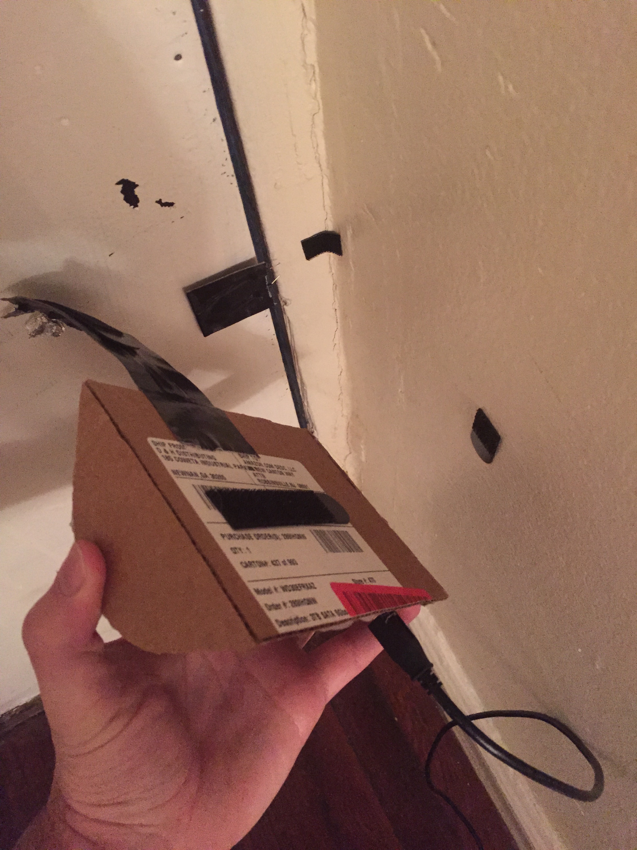
I wanted to put a lot of effort in to the design of my project so that it would really feel and look like the potentially commercial product that it is. I build a nice looking rounded case and sleek casing for the wires that connect to the door – as pictured below.

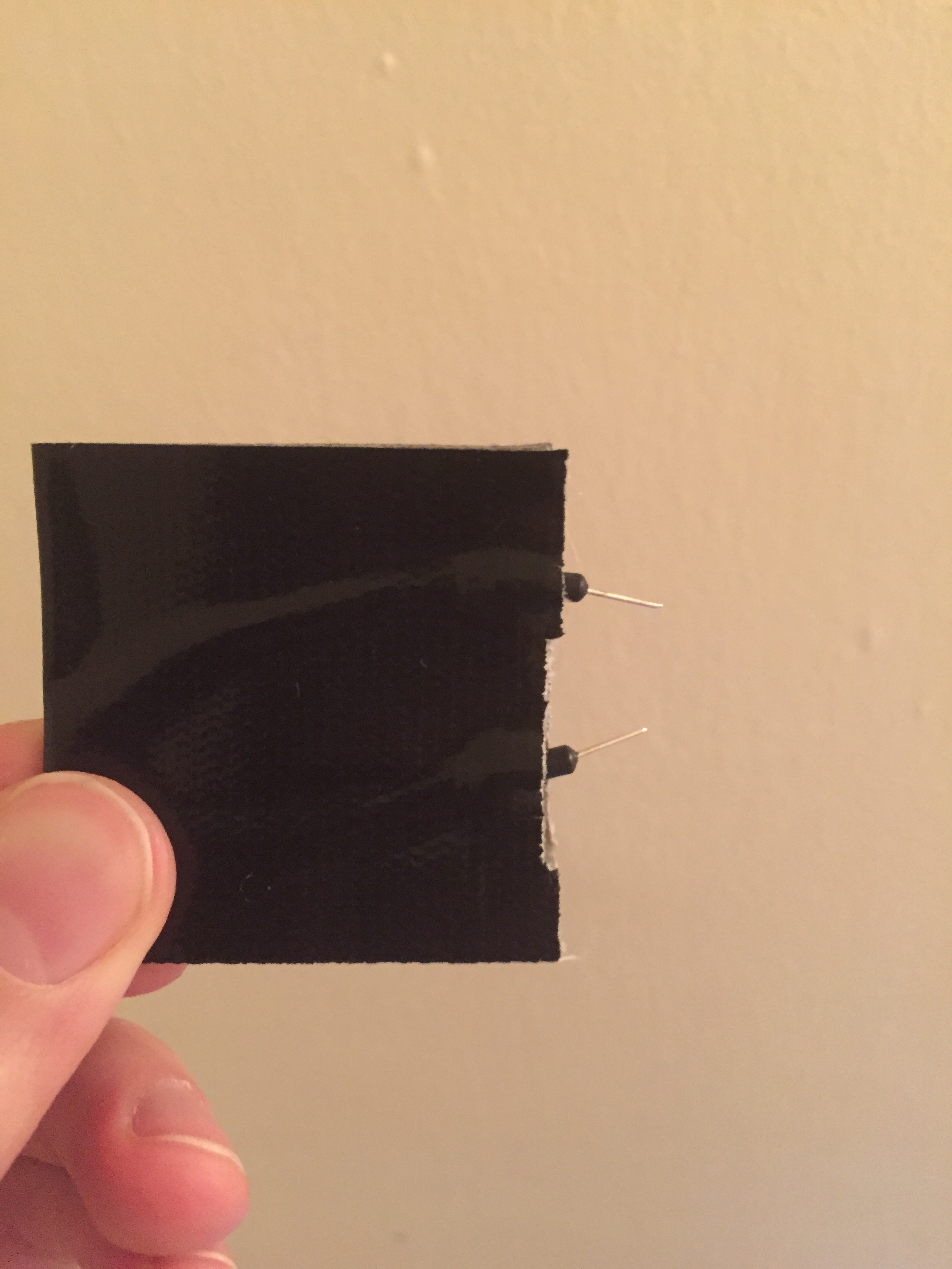
One innovation I was very proud of is that I used velcro Command strips on the back of the two pieces so the device could easily be attached/removed from multiple doors and/or stored when necessary. The velcro also allows for flexible, easy installation on any part of the door.
This is the device in operation:
In evaluating my project for its interactivity, I find that under crawfords model, there is excellent demonstration of listening and speaking. The device is monitoring constantly for the door to be opened or closed. The device responds in two different ways – instantaneously with the speaker, and remotely with a short delay via email. The thinking component of the device is a bit more limited as there is only really a simple binary thought process being performed – is the door open or closed?
The biggest thing I would do differently If I were to redo the project is to find a special part that might help the door switch perform better. I made my own switch from the wires in the arduino kit, but the contact is weak and inconsistent. I wish I had found a better solution to this.
Moving forward this switch is definitely something I could work to improve. The other main area I would want to improve is adding wireless communication. For prototyping purposes this was as much as I could manage, but before this device could really sell commercially, it would have to be working wirelessly.
Midterm Project Post 1
In looking for inspiration for this project, I wanted to examine my real life for something that I could actually use and benefit from. This led me to thinking about the door to my apartment. I live alone and often when I rush out the door I second guess myself to whether or not I properly shut the door behind me. The door is poorly weighted and doesn’t close on its own. I decided to make some kind of alert system for the door as it opens and closes.
My own most basic need was to have some kind of mobile alert so I could know for sure once I left the building that the door was shut, but I wanted to develop the idea create a more full alert system. I knew I wanted the device to send a text message or email to notify the user when the door opens or closes – and this is going to be the bigger challenge as I’ll have to research how to do this and probably download a code library add on – but I also wanted to add a simple sound alert to the system as well.
The code is definitely going to be the biggest challenge as I don’t have too much idea how to tackle the notification system. The wiring of the device seems somewhat straightforward. I’m going to create circuit across the door so it breaks when the door opens and Arduino triggers the alarm. I will either code in Arduino or Processing, or possibly both, so I might be using the serial port to communicate.
As far as design, I have a few rough ideas for building the casing for the device, and what I am most excited about is using those “hassle free hanging” velcro Command strips to attach the device to the wall (and all for it be easily moved from door to door).
Ideally I’d like the device to operate wirelessly, however that will also be a big challenge and for the extent of this project I may only make it as far as creating a wired prototype that runs off of a laptop.
